2008年3月31日 星期一

2008年3月30日 星期日
2008年3月27日 星期四
國合會2008年長期海外志工招募公告
轉貼信件
Q: 這是什麼?
A: 朋友轉來的信件,她已經出去流浪一年了
Q: 這跟這門課沒關係吧?
A: 這裡我最大
Q: %$&#@*&!
A: 什麼? 我沒聽清楚?
Q: 為什麼想要貼在這裡?
A: 純粹是不曉得要轉寄給誰,請你們幫忙轉寄一下順便也讓你們了解到有一些人過的日子跟妳們不太一樣,也許你也可以透過這種方法讓你的生命更加開闊。
加點料:http://blog.dcview.com.tw/article.php?a=BDNQNARi (這是盜連)
(以下本文)
------------------------------------------------------
您好:
財團法人國際合作發展基金會將於97年4月1日起開始招募「2008年長期海外志工」,由於您之前已填寫過報名表,因此我們另發此信給您,如果您有意願參與本年度的長期志工派遣計畫,請在4月30日前將甄選意願調查表填妥後,以:(1)傳真-(02)2876-6433;(2)電子郵件tov@icdf.org.tw;(3)郵寄-台北市天母西路62巷9號13樓等方式回覆,謝謝您。
國合會海外服務工作團「2008年長期志工」甄選意願調查表
l2008年長期志工相關作業預定時程:
4月01日~4月30日接受報名
5年01月~5月14日第一階段書面審核
5月15日~5月17日寄發第二階段甄試通知書
5月19日~5月25日擇期辦理第二階段筆試與口試
5月26日~6月06日公布錄取名單並辦理錄取說明會
6月29日~7月25日國內專業暨語言訓練
8月5日 啟程赴任
註:作業時程僅為暫訂,本會保留變動作業時程之權利。
l 聯絡電話:
陳珏吟 小姐/電話:(02)2876-8112
顏銘宏 先生/電話:(02)2876-8112
相關訊息請參考:
http://www.icdf.org.tw/chinese/c_index_news_content.asp?m001_id=467&m001_version=1
Q: 這是什麼?
A: 朋友轉來的信件,她已經出去流浪一年了
Q: 這跟這門課沒關係吧?
A: 這裡我最大
Q: %$&#@*&!
A: 什麼? 我沒聽清楚?
Q: 為什麼想要貼在這裡?
A: 純粹是不曉得要轉寄給誰,請你們幫忙轉寄一下順便也讓你們了解到有一些人過的日子跟妳們不太一樣,也許你也可以透過這種方法讓你的生命更加開闊。
加點料:http://blog.dcview.com.tw/article.php?a=BDNQNARi (這是盜連)
(以下本文)
------------------------------------------------------
您好:
財團法人國際合作發展基金會將於97年4月1日起開始招募「2008年長期海外志工」,由於您之前已填寫過報名表,因此我們另發此信給您,如果您有意願參與本年度的長期志工派遣計畫,請在4月30日前將甄選意願調查表填妥後,以:(1)傳真-(02)2876-6433;(2)電子郵件tov@icdf.org.tw;(3)郵寄-台北市天母西路62巷9號13樓等方式回覆,謝謝您。
國合會海外服務工作團「2008年長期志工」甄選意願調查表
l2008年長期志工相關作業預定時程:
4月01日~4月30日接受報名
5年01月~5月14日第一階段書面審核
5月15日~5月17日寄發第二階段甄試通知書
5月19日~5月25日擇期辦理第二階段筆試與口試
5月26日~6月06日公布錄取名單並辦理錄取說明會
6月29日~7月25日國內專業暨語言訓練
8月5日 啟程赴任
註:作業時程僅為暫訂,本會保留變動作業時程之權利。
l 聯絡電話:
陳珏吟 小姐/電話:(02)2876-8112
顏銘宏 先生/電話:(02)2876-8112
相關訊息請參考:
http://www.icdf.org.tw/chinese/c_index_news_content.asp?m001_id=467&m001_version=1
2008年3月26日 星期三
動態指標鏈結(Scheduler)
http://hunghuan.liu.googlepages.com/linked_list
(尚未完工,持續增補中)
附上另外一個以前寫的程式,沒有使用template應該比較容易看懂,相對的擴展性較差
http://hunghuan.liu.googlepages.com/DynamicQueue.h
(尚未完工,持續增補中)
附上另外一個以前寫的程式,沒有使用template應該比較容易看懂,相對的擴展性較差
http://hunghuan.liu.googlepages.com/DynamicQueue.h
2008年3月25日 星期二
2008年3月22日 星期六
2008年3月20日 星期四
實驗十 無線網路效能分析探討(二) AdHoc網路路由協定效能分析
背景知識請先看。
目前常用的無線網路路由協定有:DSDV, AODV, DSR三種。效能評估的參數為:
1. 封包送達的比率 (Packet delivery faction)
2. 封包平均延遲時間 (Average end-to-end delay of data packet)
3. 第一個封包收到的時間
Note: 這個實驗的內容與程式碼主要來自於CMU的Monarch project: Wireless and Mobility Extensions to ns-2。更詳細的參考資料在ns manual的Chapter 16
工具程式:
1. cbrgen: 是可以用來產生所需要的TCP flow或是CBR flow的Tcl Script產生器,程式位址於 ~/ns-allinone-2.29/ns2.29/indep-utils/cmu-scan-gen/cbrgen.tcl
語法:ns cbrgen.tcl [-type cbrtcp] [-nn nodes] [-seed seed][-mc connections] [-rate rate]
(用法課本上有,不贅述)
測試一下
$ns cbrgen.tcl -type cbr -nn 5 -seed 1 -mc 2 -rate 10.0 > cbr_n5_m2_r10
(ps: 課本上面的指令有一點錯誤,少了上面紅色的部分。綠色部分型態是浮點數所以要加上小數點與後面的0才不會被誤判為整數。如果不小心寫成10(整數)程式還是會執行,也會有結果產出,不過是錯誤的結果。漸漸地,在後段的學習中需要學習由結果的分析判斷模擬過程是否有錯誤的產生)。
結果
cbr_n5_m2_r10
仔細去看一下與範例所顯示的有一點不同,看起來是課本放錯範例圖了。
2. setdest: 用來產生隨機的無線網路節點的移動劇本。程式位址於 ~/ns-allinone-2.29/ns2.29/indep-utils/cmu-scan-gen/setdest目錄下。在早期的版本中使用前需要先用make產生執行檔,不過2.29版好像不需要這個步驟。
setdest命令格式如下: ./setdest -n-p -s -t -x -y > /
參數定義如下(參數的順序不重要):
-n num_of_nodes 的值指定了場景中總共有多少個節點。
-p pausetime 指定了節點運動到一個目的地後停留的時間,如果設為0,則節點不停留。
-s maxspeed 指定了節點隨機運動速度的最大值,單位是(m/s),節點的運動速度將在[0,maxspeed]中隨機選擇。
-t simtine 指定了類比場景持續的時間(單位為s)
-x maxx 指定節點運動區域的長度(x軸方向,單位為m)
-y maxy 指定節點運動區域的寬度(y軸方向,單位為m)
>/ 指定了生成場景的輸出檔。
測試
$ ./setdest -n 2 -p 0.0 -M 20.0 -t 10 -x 300 -y 300 > scen_2n_0p_20M_10t_300_300
(note: 另外有一個參數 -v 可以設定setdest的版本,version 2會多出幾個參數需要給定,可以直接打入 ./setdest 觀看使用說明)
範例一
這個實驗由100個無線節點所組成,模擬時間為100秒,pause time為100秒(這等於靜止不動),使用CBR資料流,最大連線數目10條,每一條flow每秒送出10個封包。
使用cbrgen產生traffic pattern
$ns cbrgen.tcl -type cbr -nn 100 -seed 1 -mc 10 -rate 10.0 > cbr_n100_m10_r10
使用setdest產生無線網路移動場景
./setdest.exe -n 100 -p 100.0 -M 10.0 -t 100 -x 300 -y 300 > scen_100n_100p_10M_100t_300_300
(note: setdest和cbrgen的參數設定需要一致,另外有一些參數是無效的,例如這個實驗中所有的node都是靜止不動的,所以移動速度的設定就沒有影響。)
將所產生的檔案名稱放入book2/lab10/lab10_1.tcl中的適當位置
#設定traffic pattern檔案
set opt(cp) "cbr_n100_m10_r10"
#設定節點移動場景
set opt(sc) "scen_100n_100p_10M_100t_300_300"
然後執行 $ns lab10_1.tcl DSDV (使用DSDV作為路由協定)
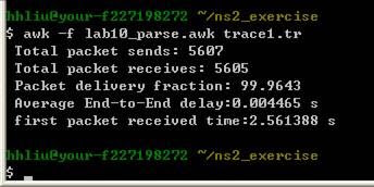
大約三分鐘就跑完了,還算很快。看結果
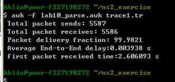
然後再試試 AODV的效能: $ns lab10_1.tcl AODV
DSR: $ns lab10_1.tcl DSR
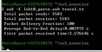
效能參數都差不多,實驗量太少不足以說明什麼。另外因為網路節點是靜止不動的也沒有錯誤模型被加入以至於在delivery ratio方面都是100%。
範例二
改成移動模型(pause time = 0),然後範圍大一點(500 x 500)其餘皆相同。
./setdest.exe -n 100 -p 0.0 -M 10.0 -t 100 -x 500 -y 500 > scen_100n_0p_10M_100t_500_500
lab10_2.tcl的程式碼與lab10_1.tcl完全相同,除了載入的移動劇本檔案不同以外。
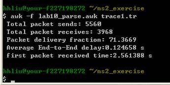
$ns lab10_2.tcl DSDV
$ns lab10_2.tcl AODV
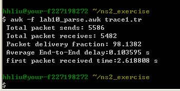
$ns lab10_2.tcl DSR
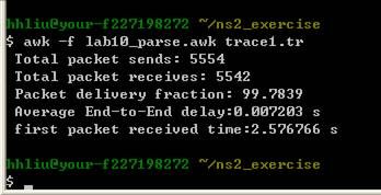
這裡就可以稍微判定一下,在移動的環境下DSDV表現不如DSR和AODV。
目前常用的無線網路路由協定有:DSDV, AODV, DSR三種。效能評估的參數為:
1. 封包送達的比率 (Packet delivery faction)
2. 封包平均延遲時間 (Average end-to-end delay of data packet)
3. 第一個封包收到的時間
Note: 這個實驗的內容與程式碼主要來自於CMU的Monarch project: Wireless and Mobility Extensions to ns-2。更詳細的參考資料在ns manual的Chapter 16
工具程式:
1. cbrgen: 是可以用來產生所需要的TCP flow或是CBR flow的Tcl Script產生器,程式位址於 ~/ns-allinone-2.29/ns2.29/indep-utils/cmu-scan-gen/cbrgen.tcl
語法:ns cbrgen.tcl [-type cbrtcp] [-nn nodes] [-seed seed][-mc connections] [-rate rate]
(用法課本上有,不贅述)
測試一下
$ns cbrgen.tcl -type cbr -nn 5 -seed 1 -mc 2 -rate 10.0 > cbr_n5_m2_r10
(ps: 課本上面的指令有一點錯誤,少了上面紅色的部分。綠色部分型態是浮點數所以要加上小數點與後面的0才不會被誤判為整數。如果不小心寫成10(整數)程式還是會執行,也會有結果產出,不過是錯誤的結果。漸漸地,在後段的學習中需要學習由結果的分析判斷模擬過程是否有錯誤的產生)。
結果
cbr_n5_m2_r10
仔細去看一下與範例所顯示的有一點不同,看起來是課本放錯範例圖了。
2. setdest: 用來產生隨機的無線網路節點的移動劇本。程式位址於 ~/ns-allinone-2.29/ns2.29/indep-utils/cmu-scan-gen/setdest目錄下。在早期的版本中使用前需要先用make產生執行檔,不過2.29版好像不需要這個步驟。
setdest命令格式如下: ./setdest -n
參數定義如下(參數的順序不重要):
-n num_of_nodes 的值指定了場景中總共有多少個節點。
-p pausetime 指定了節點運動到一個目的地後停留的時間,如果設為0,則節點不停留。
-s maxspeed 指定了節點隨機運動速度的最大值,單位是(m/s),節點的運動速度將在[0,maxspeed]中隨機選擇。
-t simtine 指定了類比場景持續的時間(單位為s)
-x maxx 指定節點運動區域的長度(x軸方向,單位為m)
-y maxy 指定節點運動區域的寬度(y軸方向,單位為m)
>
測試
$ ./setdest -n 2 -p 0.0 -M 20.0 -t 10 -x 300 -y 300 > scen_2n_0p_20M_10t_300_300
(note: 另外有一個參數 -v 可以設定setdest的版本,version 2會多出幾個參數需要給定,可以直接打入 ./setdest 觀看使用說明)
範例一
這個實驗由100個無線節點所組成,模擬時間為100秒,pause time為100秒(這等於靜止不動),使用CBR資料流,最大連線數目10條,每一條flow每秒送出10個封包。
使用cbrgen產生traffic pattern
$ns cbrgen.tcl -type cbr -nn 100 -seed 1 -mc 10 -rate 10.0 > cbr_n100_m10_r10
使用setdest產生無線網路移動場景
./setdest.exe -n 100 -p 100.0 -M 10.0 -t 100 -x 300 -y 300 > scen_100n_100p_10M_100t_300_300
(note: setdest和cbrgen的參數設定需要一致,另外有一些參數是無效的,例如這個實驗中所有的node都是靜止不動的,所以移動速度的設定就沒有影響。)
將所產生的檔案名稱放入book2/lab10/lab10_1.tcl中的適當位置
#設定traffic pattern檔案
set opt(cp) "cbr_n100_m10_r10"
#設定節點移動場景
set opt(sc) "scen_100n_100p_10M_100t_300_300"
然後執行 $ns lab10_1.tcl DSDV (使用DSDV作為路由協定)
大約三分鐘就跑完了,還算很快。看結果
然後再試試 AODV的效能: $ns lab10_1.tcl AODV
DSR: $ns lab10_1.tcl DSR
效能參數都差不多,實驗量太少不足以說明什麼。另外因為網路節點是靜止不動的也沒有錯誤模型被加入以至於在delivery ratio方面都是100%。
範例二
改成移動模型(pause time = 0),然後範圍大一點(500 x 500)其餘皆相同。
./setdest.exe -n 100 -p 0.0 -M 10.0 -t 100 -x 500 -y 500 > scen_100n_0p_10M_100t_500_500
lab10_2.tcl的程式碼與lab10_1.tcl完全相同,除了載入的移動劇本檔案不同以外。
$ns lab10_2.tcl DSDV
$ns lab10_2.tcl AODV
$ns lab10_2.tcl DSR
這裡就可以稍微判定一下,在移動的環境下DSDV表現不如DSR和AODV。
2008年3月19日 星期三
隨機變數的產生
電腦裡面的亂數產生器可以產生[1 ~ RandMAX]範圍內的數字,我們可以把它視為是一個Uniform Distribution的產生器。如果我們在模擬的過程需要使用到其他機率分佈的產生器則需要使用以下的過程:
假設我們需要產生一個連續的r. v. X,其具有distribution function F。
F 是嚴格遞增的函數(strictly increasing), i.e., if x1 <= x2, then 0 < F(x1) <= F(x2) <1。
令invF表示 F 的反函數,則產生X的隨機變數的程序為:
1. Generate U ~ U(0, 1)
2. Return X = invF(U)
remark: P(X <= x) = P(invF(U) <= x) = P(U <= F(x)) = F(x)
Examle. Let X have the exponential distribution with mean a. The distribution function is
F(x) = 1 - exp{ -x/a }, if x >= 0; 0, otherwise
so invF(u) = -a.ln(1 - u)
程式碼
Truncated density
考慮一個狀況,我們想要使用程式產生網路封包的大小(size)用來模擬網路的效能,通常可以假設封包的大小是依據exponential distribution。不過網路上的封包不會無限大,也不可能是0,所以需要限定所產生出來封包的上下限。How to do it?
define the truncated density
f*(x) = f(x) / (F(b) - F(a)), if a <= x <= b; 0, otherwise
the corresponding truncated distribution function is
F*(x) = ((F(x) - F(a)) / ((F(b) - F(a)), if a <= x <= b; 0, if x < a; 1, if b < x
The algorithm for generating an X having distribution function F* is as follows:
1. Generate U ~ U(0, 1).
2. Let V = F(a) + [F(b) - F(a)]U.
3. Return X = invF(V)
有兩個問題給你們想想:
1. 經過裁剪以後,mean與variance的改變為何?
2. 為何上述演算法的第三項是X = invF(V) 而不是X = invF*(V)?
NS2中的亂數產生器
NS2目前提供Pareto, Constant, Uniform, Exponential, 和 HyperExponintial分佈,程式碼放在
~/ns-allinone-2.29/ns-2.29/tools目錄下。
NS2中使用的方法:
1. 設定seed
set rng [new RNG]
$rng seed 1
2. 設定分佈
a. Pareto :
set r1 [new RandomVariable/Pareto]
$r1 use-rng $rng
$r1 set avg_ 10.0
$r1 set shape_ 1.2
b. Constant :
set r2 [new RandomVariable/Constant]
$r2 use-rng $rng
$r2 set avg_ 10.0
c. Uniform :
set r3 [new RandomVariable/Uniform]
$r3 use-rng $rng
$r3 set min_ 0.0
$r3 set max_ 10.2
d. Exponential :
set r4 [new RandomVariable/Exponential]
$r4 use-rng $rng
$r4 set avg_ 10.0
e. Hyperexponential :
set r5 [new RandomVariable/HyperExponential]
$r5 use-rng $rng
$r5 set avg_ 1.0
$r5 set cov_ 5.0
假設我們需要產生一個連續的r. v. X,其具有distribution function F。
F 是嚴格遞增的函數(strictly increasing), i.e., if x1 <= x2, then 0 < F(x1) <= F(x2) <1。
令invF表示 F 的反函數,則產生X的隨機變數的程序為:
1. Generate U ~ U(0, 1)
2. Return X = invF(U)
remark: P(X <= x) = P(invF(U) <= x) = P(U <= F(x)) = F(x)
Examle. Let X have the exponential distribution with mean a. The distribution function is
F(x) = 1 - exp{ -x/a }, if x >= 0; 0, otherwise
so invF(u) = -a.ln(1 - u)
程式碼
Truncated density
考慮一個狀況,我們想要使用程式產生網路封包的大小(size)用來模擬網路的效能,通常可以假設封包的大小是依據exponential distribution。不過網路上的封包不會無限大,也不可能是0,所以需要限定所產生出來封包的上下限。How to do it?
define the truncated density
f*(x) = f(x) / (F(b) - F(a)), if a <= x <= b; 0, otherwise
the corresponding truncated distribution function is
F*(x) = ((F(x) - F(a)) / ((F(b) - F(a)), if a <= x <= b; 0, if x < a; 1, if b < x
The algorithm for generating an X having distribution function F* is as follows:
1. Generate U ~ U(0, 1).
2. Let V = F(a) + [F(b) - F(a)]U.
3. Return X = invF(V)
有兩個問題給你們想想:
1. 經過裁剪以後,mean與variance的改變為何?
2. 為何上述演算法的第三項是X = invF(V) 而不是X = invF*(V)?
NS2中的亂數產生器
NS2目前提供Pareto, Constant, Uniform, Exponential, 和 HyperExponintial分佈,程式碼放在
~/ns-allinone-2.29/ns-2.29/tools目錄下。
NS2中使用的方法:
1. 設定seed
set rng [new RNG]
$rng seed 1
2. 設定分佈
a. Pareto :
set r1 [new RandomVariable/Pareto]
$r1 use-rng $rng
$r1 set avg_ 10.0
$r1 set shape_ 1.2
b. Constant :
set r2 [new RandomVariable/Constant]
$r2 use-rng $rng
$r2 set avg_ 10.0
c. Uniform :
set r3 [new RandomVariable/Uniform]
$r3 use-rng $rng
$r3 set min_ 0.0
$r3 set max_ 10.2
d. Exponential :
set r4 [new RandomVariable/Exponential]
$r4 use-rng $rng
$r4 set avg_ 10.0
e. Hyperexponential :
set r5 [new RandomVariable/HyperExponential]
$r5 use-rng $rng
$r5 set avg_ 1.0
$r5 set cov_ 5.0
實驗九 無線網路效能分析探討(一) 隱藏節點和暴露節點問題
實驗六、七、八想先讓你們去傷一下腦筋,學習一下自己解決問題,有時間再補說明。
實驗九 無線網路效能分析探討(一) 隱藏節點和暴露節點問題
背景知識
1. 隱藏節點問題
2. 暴露節點問題
傳輸模型(propagation model)與門檻(threshold)
1. Free Space Path Loss

程式碼放在 ~ns/mobile/propagation.h, propagation.cc
2. Two Ray Ground
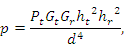
程式碼放在 ~ns/mobile/tworayground.h, tworayground.cc
3. Shadowing
(in-door) ~ns/mobile/shadowing.h, shadowing.cc
4. Threshold
以上的model基本上可以看成距離的函數 f(d),沒有機率的成份在裡面。
~ns/mac/wireless-phy.h, wireless-phy.cc
實驗步驟
先利用一些獨立的小工具程式來計算模擬所需要的設定參數,這些小工具放在 ~/ns-allinone-2.29/ns-2.29/indep-utils下面。這裡需要用的threshold.cc, threshold.exe在~/ns-allinone-2.29/ns-2.29/indep-utils/propagation目錄下。
先執行一次計算若是有效距離是250公尺的時候需要設定的參數有哪些
./threshold.exe -m TwoRayGround 250
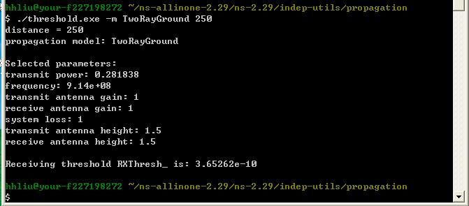
這些結果有一些是需要事先設定的,例如antenna gain and height。還有一些是無關的,例如frequency。所以如果要得到適合的結果需要修改程式內容然後重新編譯。這裡我試試改成frequency = 2.3 GHz, transmit antenna height = 30 m, transmit power = 0.1 W
重新編譯
$g++ -lm threshold.cc -o threshold
然後在計算一次
./threshold.exe -m TwoRayGround 250
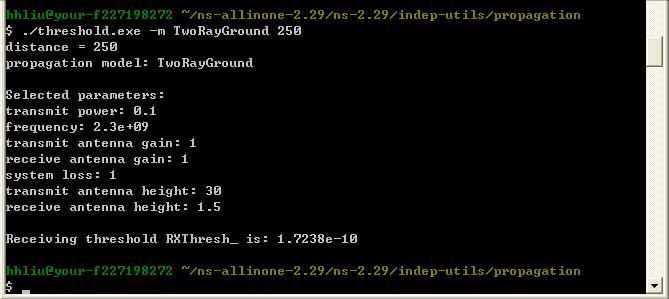
就會得到不同的結果了。
後面的實驗照著書跑吧,需要注意的是當你們在做實驗的時候也許會套用現成的模型,這個模型所使用的參數應該需要檢查一下是否符合系統設置的環境,例如:
test_2nodes.tcl中
#天線高度
Antenna/OmniAntenna set Z_ 1.5
#天線增益
Antenna/OmniAntenna set Gt_ 1.0
Antenna/OmniAntenna set Gr_ 1.0
#按照threshold所設定
Phy/WirelessPhy set RXThresh_ 3.652e-10
Phy/WirelessPhy set bandwidth_ 2e6
Phy/WirelessPhy set Pt_ 0.28183815
Phy/WirelessPhy set freq_ 914e+6
Phy/WirelessPhy set L_ 1.0
可以觀察一下有哪些和目前所使用的IEEE 802.11系統參數不同的。
實驗九 無線網路效能分析探討(一) 隱藏節點和暴露節點問題
背景知識
1. 隱藏節點問題
2. 暴露節點問題
傳輸模型(propagation model)與門檻(threshold)
1. Free Space Path Loss
程式碼放在 ~ns/mobile/propagation.h, propagation.cc
2. Two Ray Ground
程式碼放在 ~ns/mobile/tworayground.h, tworayground.cc
3. Shadowing
(in-door) ~ns/mobile/shadowing.h, shadowing.cc
4. Threshold
以上的model基本上可以看成距離的函數 f(d),沒有機率的成份在裡面。
~ns/mac/wireless-phy.h, wireless-phy.cc
實驗步驟
先利用一些獨立的小工具程式來計算模擬所需要的設定參數,這些小工具放在 ~/ns-allinone-2.29/ns-2.29/indep-utils下面。這裡需要用的threshold.cc, threshold.exe在~/ns-allinone-2.29/ns-2.29/indep-utils/propagation目錄下。
先執行一次計算若是有效距離是250公尺的時候需要設定的參數有哪些
./threshold.exe -m TwoRayGround 250
這些結果有一些是需要事先設定的,例如antenna gain and height。還有一些是無關的,例如frequency。所以如果要得到適合的結果需要修改程式內容然後重新編譯。這裡我試試改成frequency = 2.3 GHz, transmit antenna height = 30 m, transmit power = 0.1 W
重新編譯
$g++ -lm threshold.cc -o threshold
然後在計算一次
./threshold.exe -m TwoRayGround 250
就會得到不同的結果了。
後面的實驗照著書跑吧,需要注意的是當你們在做實驗的時候也許會套用現成的模型,這個模型所使用的參數應該需要檢查一下是否符合系統設置的環境,例如:
test_2nodes.tcl中
#天線高度
Antenna/OmniAntenna set Z_ 1.5
#天線增益
Antenna/OmniAntenna set Gt_ 1.0
Antenna/OmniAntenna set Gr_ 1.0
#按照threshold所設定
Phy/WirelessPhy set RXThresh_ 3.652e-10
Phy/WirelessPhy set bandwidth_ 2e6
Phy/WirelessPhy set Pt_ 0.28183815
Phy/WirelessPhy set freq_ 914e+6
Phy/WirelessPhy set L_ 1.0
可以觀察一下有哪些和目前所使用的IEEE 802.11系統參數不同的。
2008年3月18日 星期二
2008年3月15日 星期六
[公告]未發文名單_第四週小計
9426111,9326227,9428122
三位同學現在仍未見到你們發表實驗一
請問是否有blogger操作上的困難
請依課程要求須完成至少10個課本實驗與1個C語言實驗
請大家自行規劃
**勿於期末趕進度一次貼上
三位同學現在仍未見到你們發表實驗一
請問是否有blogger操作上的困難
請依課程要求須完成至少10個課本實驗與1個C語言實驗
請大家自行規劃
**勿於期末趕進度一次貼上
2008年3月14日 星期五
實驗五 無線網路封包傳輸遺失模型
這個實驗討論無線網路封包傳輸遺失模型,在無線通道部分採用Gilbert-Elliott模型 (GE model)
- J. P. Ebert, A. Willing, A Gilbert-Elliot Bit Error Model and the Efficient Use in Packet Level Simulation, Technical Report, TKN-99-002, Technical University of Berlin, March 1999.
- H. S. Wand, N. Moayeri, Finite state morkov channel - a useful model for radio communication channel, IEEE Trans. on Vehicular Tech., 44 (1), 163-171, Feb. 1995.
- 如何修改現有的模組,加入自己需要的功能
- 如何設計具有兩個或兩個以上的位址空間的網路
作者直接修改了wireless-phy.cc 和 wireless-phy.h這兩個檔案 (class WirelessPhy),另外一種方式是由WirelessPhy衍生下一個類別,不過如過是這樣做還需要再產生相對應的Otcl linkage, 程序上是比較複雜不過可在用性與程式的擴充性會比較好。
wireless-phy.cc 和 wireless-phy.h這兩個檔案放在C:\cygwin\home\hhliu\ns-allinone-2.29\ns-2.29\mac目錄下,很容易可以找到。目錄下面有保留原始的檔案,可以拿來做比較。
加入的程式碼我可以找到的部分如下(紅色字體部分):
另外關於定址的部分,Tcl程式碼如下:
#若模擬的環境,是單純的有線網路,或無線網路,定址的方是使用flat即可(default設定)
#但是若包含了有線網路和無線網路,則就需要使用hierarchial addressing的方式定址 [ref]
$ns_ node-config -addressType hierarchical
#設定有兩個domain(第一個domain是有線網路,第二個是無線網路)
AddrParams set domain_num_ 2 ; # AddrParams 是類別名稱
# Class AddrParams is used to store the topology hierarchy like number of levels of hierarchy,
# number of areas in each levellike number of domains, number of clusters and number of nodes
# in each cluster.
#每個domain各有一個cluster(每一個domain只包含一個子網路)
lappend cluster_num 1 1
AddrParams set cluster_num_ $cluster_num
#而在第一個domain,其第一個cluster中,只有一個有線網路節點#而在地二個domain,其第一個cluster中,會有兩個無線網路節點,基地台算無線節點
lappend eilastlevel 1 2
AddrParams set nodes_num_ $eilastlevel
這個部份的程式說明還是先擱置,以後再說明。
實驗結果:
Scenario 1.
PG = 0.2, loss-model = 0, comm_type = 0 (multicast)
packet loss ratio = (12350 - 12349) / 12350 = 8.1 e-5, 這個結果和課本呈現的差很多。
再跑一次,結果一樣 =.=?
Scenario 2.
packet loss ratio = (12350 - 12350) / 12350 = 0, ====> 看來問題大了
Scenario 3
packet loss ratio = (12350 - 12350) / 12350 = 0, ====> >.<"
是什麼原因造成的錯誤我先暫時不去debug了,請執行看看如果結果跟我的一樣後續再來抓bug。
2008年3月13日 星期四
2008年3月12日 星期三
實驗四 網路效能量測
實驗四之一(有線網路)的主題:
$awk 'AWK程式' 資料檔檔名
然後用gnuplot畫圖,如下:

當然我們也可以用Matlab或是Excel畫圖。

- 計算CBR的封包遺失率 (cbr packet loss rate)
- 計算封包延遲時間 (cbr delay)
- 計算抖動率 (jitter)
- UDP吞吐量 (UDP throughput)
- TCP吞吐量 (TCP throughput)
實驗四之二(無線網路)的主題:
- 計算CBR的封包遺失率 (cbr packet loss rate)
- 計算封包延遲時間 (cbr delay)
- 計算抖動率 (jitter)
- 吞吐量 (throughput)
實驗四之一 (有線網路)和實驗二大致相同,可以使用nsBench, NSG2來產生.tcl檔案,或是直接拷貝CD中的範例。
set nd [open out.tr w]
$ns trace-all $nd #這段程式碼開啟一個模擬過程記錄檔,用來記錄封包傳送的過程
NS2所提供的模擬過程記錄檔格式並不是統一的,模擬環境若是全部都是有線的,其紀錄檔格式如下所示:

有線網路環境下的模擬過程記錄檔範例:
+ 0.1 1 2 cbr 1000 ------- 2 1.0 3.1 0 0
#在0.1秒的時候一個cbr資料封包,大小是1000bytes,封包的序號(seq. no.)為0,封包的編號(id.)為0。從node 1傳送出來進入了連結到node 2 的link的queue當中。這個封包屬於資料流2,它的來源端是1.0,表示node 1的第0個port;目的端是3.1,表示node 3的第1個port。
- 0.1 1 2 cbr 1000 ------- 2 1.0 3.1 0 0
+ 0.108 1 2 cbr 1000 ------- 2 1.0 3.1 1 1
- 0.108 1 2 cbr 1000 ------- 2 1.0 3.1 1 1
r 0.114 1 2 cbr 1000 ------- 2 1.0 3.1 0 0
+ 0.114 2 3 cbr 1000 ------- 2 1.0 3.1 0 0
- 0.114 2 3 cbr 1000 ------- 2 1.0 3.1 0 0
通常我們用awk將需要的資料從trace檔案中分離出來,同樣的工具還有grep, seed, perl。perl功能更強大,進階時建議使用。當然也可以用matlab, excel等。
$awk 'AWK程式' 資料檔檔名
然後用gnuplot畫圖,如下:

當然我們也可以用Matlab或是Excel畫圖。

2008年3月11日 星期二
2008年3月10日 星期一
2008年3月9日 星期日
2008年3月8日 星期六
NS Simulator for Beginners
一些有用的參考資料,陸續整理在這裡
這三篇文件努力把它看完應該可以對NS2的使用有一些了解
認識NS2 (浙江工業大學軟體學院劉世華)
NS Simulator for Beginners
NS by Examples (html) (ps)
其他:
CprE 543x – ns-2 Tutorial (ppt)
AWK Tutorial Guide
Perl
另外一些參考連結:
ns2 tutorial
ns2 Manual (最新的手冊,進階者需要閱讀。419頁)
NS2 教學手冊 ( NS2 Learning Guide) (金門技術學院柯志亨老師的網站)
The Network Simulator - ns-2
這三篇文件努力把它看完應該可以對NS2的使用有一些了解
認識NS2 (浙江工業大學軟體學院劉世華)
NS Simulator for Beginners
NS by Examples (html) (ps)
其他:
CprE 543x – ns-2 Tutorial (ppt)
AWK Tutorial Guide
Perl
另外一些參考連結:
ns2 tutorial
ns2 Manual (最新的手冊,進階者需要閱讀。419頁)
NS2 教學手冊 ( NS2 Learning Guide) (金門技術學院柯志亨老師的網站)
The Network Simulator - ns-2
2008年3月7日 星期五
2008年3月6日 星期四
2008年3月5日 星期三
2008年3月3日 星期一
實驗二 nsBench and TCL
http://hunghuan.liu.googlepages.com/nsbench
TCL語法的解釋:(摘錄自 NS by Example)
TCL語法的解釋:(摘錄自 NS by Example)
 set ns [new Simulator]: generates an NS simulator object instance, and assigns it to variablens (italics is used for variables and values in this section). What this line does is thefollowing:
• Initialize the packet format (ignore this for now)
• Create a scheduler (default is calendar scheduler)
• Select the default address format (ignore this for now)
The "Simulator" object has member functions that do the following:
• Create compound objects such as nodes and links (described later)
• Connect network component objects created (ex. attach-agent)
• Set network component parameters (mostly for compound objects)
• Create connections between agents (ex. make connection between a "tcp" and "sink")
• Specify NAM display options
• Etc.
Most of member functions are for simulation setup (referred to as plumbing functions in the Overview section) and scheduling, however some of them are for the NAM display. The "Simulator" object member function implementations are located in the "ns-2/tcl/lib/nslib.tcl" file.
$ns color fid color: is to set color of the packets for a flow specified by the flow id (fid). This member function of "Simulator" object is for the NAM display, and has no effect on theactual simulation.
$ns namtrace-all file-descriptor: This member function tells the simulator to record simulation traces in NAM input format. It also gives the file name that the trace will be written to later by the command $ns flush-trace. Similarly, the member function trace-all is for recording the simulation trace in a general format.
proc finish {}: is called after this simulation is over by the command $ns at 5.0 "finish". Inthis function, post-simulation processes are specified.
set n0 [$ns node]: The member function node creates a node. A node in NS is compound object made of address and port classifiers (described in a later section). Users can create a node by separately creating an address and a port classifier objects and connecting them together. However, this member function of Simulator object makes the job easier. To see how a node is created, look at the files: "ns-2/tcl/libs/ns-lib.tcl" and "ns-2/tcl/libs/nsnode.tcl".
$ns duplex-link node1 node2 bandwidth delay queue-type: creates two simplex links of specified bandwidth and delay, and connects the two specified nodes. In NS, the output queue of a node is implemented as a part of a link, therefore users should specify the queue type when creating links. In the above simulation script, DropTail queue is used. If the reader wants to use a RED queue, simply replace the word DropTail with RED. The NS implementation of a link is shown in a later section. Like a node, a link is a compound object, and users can create its sub-objects and connect them and the nodes. Link source codes canbe found in "ns-2/tcl/libs/ns-lib.tcl" and "ns-2/tcl/libs/ns-link.tcl" files. One thing to note is that you can insert error modules in a link component to simulate a lossy link (actually users can make and insert any network objects). Refer to the NS documentation to find out how todo this.
$ns queue-limit node1 node2 number: This line sets the queue limit of the two simplex links that connect node1 and node2 to the number specified. At this point, the authors do not know how many of these kinds of member functions of Simulator objects are available and what they are. Please take a look at "ns-2/tcl/libs/ns-lib.tcl" and "ns-2/tcl/libs/ns-link.tcl", or NS documentation for more information.
$ns duplex-link-op node1 node2 ...: The next couple of lines are used for the NAM display. To see the effects of these lines, users can comment these lines out and try the simulation.
Now that the basic network setup is done, the next thing to do is to setup traffic agents such as TCP and UDP, traffic sources such as FTP and CBR, and attach them to nodes and agents respectively.
set tcp [new Agent/TCP]: This line shows how to create a TCP agent. But in general, users can create any agent or traffic sources in this way. Agents and traffic sources are in fact basic objects (not compound objects), mostly implemented in C++ and linked to OTcl. Therefore, there are no specific Simulator object member functions that create these object instances. To create agents or traffic sources, a user should know the class names these objects (Agent/TCP, Agnet/TCPSink, Application/FTP and so on). This information can be found inthe NS documentation or partly in this documentation. But one shortcut is to look at the "ns-2/tcl/libs/ns-default.tcl" file. This file contains the default configurable parameter value settings for available network objects. Therefore, it works as a good indicator of what kind of network objects are available in NS and what are the configurable parameters.
$ns attach-agent node agent: The attach-agent member function attaches an agent object created to a node object. Actually, what this function does is call the attach member function of specified node, which attaches the given agent to itself. Therefore, a user can do the samething by, for example, $n0 attach $tcp. Similarly, each agent object has a member function attach-agent that attaches a traffic source object to itself.
$ns connect agent1 agent2: After two agents that will communicate with each other arecreated, the next thing is to establish a logical network connection between them. This line establishes a network connection by setting the destination address to each others' network and port address pair.
Assuming that all the network configuration is done, the next thing to do is write a simulation scenario (i.e. simulation scheduling). The Simulator object has many scheduling member functions. However, the one that is mostly used is the following:
$ns at time "string": This member function of a Simulator object makes the scheduler(scheduler_ is the variable that points the scheduler object created by [new Scheduler] command at the beginning of the script) to schedule the execution of the specified string at given simulation time. For example, $ns at 0.1 "$cbr start" will make the scheduler call a start member function of the CBR traffic source object, which starts the CBR to transmit data. In NS, usually a traffic source does not transmit actual data, but it notifies the underlying agent that it has some amount of data to transmit, and the agent, just knowing how much of the data to transfer, creates packets and sends them.
After all network configuration, scheduling and post-simulation procedure specifications are done, the only thing left is to run the simulation. This is done by $ns run.
訂閱:
文章 (Atom)